Drawings and Surveys
Overview
Drawings (also known as technical drawings) visually communicate how something functions or is constructed. These days they’re usually prepared using computer aided design software (CAD).
If your renovation works are minor and really just involve something like internal redecoration works, you likely won’t need any drawings unless you want some kind of room layout or interior design plan drawn up.
If your renovation works are going to involve anything more than that, you’ll need to consider whether you need some or all of the following.
If you need to:
Measured Surveys
Before any drawings are prepared, a measured survey is ordinarily first carried out.
To survey just means to gather information about something. In the context of technical drawings, a survey (often called a measured survey) involves the measurement of the relevant parts of your existing property. Those measurements are then used to accurately depict the relevant parts of your property in digital format, which then serves as the base for the various drawings.
Often doing a measured survey is handled by whomever you appoint to prepare your architectural drawings.
If you wanted to get your own measured survey done however (potentially more cost effective), there are companies out there who provide measured survey services. A quick Google will bring up some good options.
Many surveyors these days use 3D laser scanners (they just set them up in the relevant space and all spatial data is captured and they then produce measured survey drawings from this data).
You could alternatively take a DIY approach and use a measuring tape with a laser function. Bear in mind though that all subsequent drawings will be based on these measurements so it’s absolutely vital that they’re accurate.
The Key Drawings
Architectural Planning Drawings
Architectural planning design drawings will likely be one of the first things you’ll need to get organised, particularly if your project will require any kind of planning permission or lawful development certificate (aka a certificate of permitted development or a certificate of lawful development).
They’re used to develop and communicate a design and for planning permission / lawful development certificate applications. If you’re not yet sure if your project will require planning permission or a lawful development certificate, have a look at our Planning Permission page and check the Planning Portal website, which has very helpful guides.
The drawings will set out the project design plan, depicting the building both as it exists currently and how it will be after the proposed building works have been completed. They reflect various perspectives, including front and rear elevation views, bird’s eye view from above, floor plans and cross-sectional views. They’ll also incorporate key information like dimensions to a specified scale.
As an example, here are snapshots of our most recent renovation, showing the before and after of a ground floor rear extension of a Victorian terraced house, as well as before and after cross-sections.
Ground Floor Plan — Before

Ground Floor Plan — After

Cross-section — Before

Cross-section — After

Various professionals can prepare architectural planning drawings, not just architects
Most people immediately think they need an architect. Architects are fully trained and qualified in all aspects of architecture, and are required to be listed on the ARB’s Register of Architects. If you need one, you can search for members via the Architect’s Register or the RIBA website.
There are other professionals who can prepare architectural drawings for you though.
Architectural Technologists will have completed an Architectural Technology program accredited by the Chartered Institute of Architectural Technologists. They focus more on the technical end of things. If you need one, you can search on the CIAT website.
Architectural Designers are designers who design buildings or parts of buildings. They’re not qualified or registered like an architect or architectural technologist but may nevertheless have plenty of experience and skills and may be all you need for your renovation project. If you need one, best bet is to just Google for architectural designers in your area. There are many located throughout the UK as well as some nationwide.
Design and Build Companies are contractor companies that provide architectural design services along with the usual construction services. If you need one, just Google for design and build companies in your area, use FMB, and/or try to get recommendations from family, friends and neighbours. See our Finding and Engaging Good Contractors page for more information about lining up decent contractors.
Who you elect to go with will depend on your budget and what kind of work you want to have done.
If your project is a straightforward loft conversion that’ll inevitably be very similar to plenty of others done in your area, you probably don’t really need to pay a lot more money to engage an architect. An architectural designer or design and build company would do the job fine.
If you’re doing something like an extension that for some reason requires more complex technical input, maybe an architectural technologist would be the best option.
If you particularly want to try something fairly innovative with reconfiguring your property and adding various nice external features, then maybe a fully fledged architect is the way to go.
Cost is always a factor too of course so maybe you’ll be better off contacting a few of each kind and see what the balance is in terms of likely cost.
Architectural planning drawings serve as the base for Other drawings
Whoever you go with, just a quick warning about drawings more generally. While measured surveys will form the base for the architectural planning drawings, the architectural plans in turn serve as the base for various other drawings. Likewise, other professionals in the process will follow them for what they have to do; often very closely.
You should therefore be careful about what the architectural planning drawings do and do not communicate and always ensure that others reviewing them know where there are differences or omissions.
It’s Not A Study?!
We’ve had a number of problems in the past where others involved in the process just go by whatever the architectural planning drawings depict thinking that the layout or function of a room would be what was depicted when it wasn’t.
Look at the excerpt above of our architectural drawings of the finished ground floor extension. Do you see that the rear reception room says that it’s a study? It isn’t. It wasn’t. It was never going to be. The designer at the architectural firm just called it a study and threw in the diagrammatic table and chair for some reason.
It seemed inconsequential at the time until later in the process when someone else in their team who was supposed to draw up an electrical and heating plan, ended up putting all sorts of unnecessary electrics, Internet connections and lighting in that area because they thought it was going to be a study.
We similarly had a few other issues with other aspects of the drawings. For example, earlier iterations of these architectural planning drawings showed a very different layout for the kitchen units and dining table. Those resulted in even bigger problems with a number of other professionals involved in the process.
The point is ultimately that you ideally need the architectural planning drawings to be as accurate as possible, not just for what is required for planning permission purposes but also everything else.
There may be situations when you actually don’t know what a room layout will be or even what it’ll be used for though.
In those situations, at least make clear in the drawings (by digital text or even by hand if necessary) that the relevant part of the drawings is purely for illustrative purposes and will likely change.
Structural Drawings
Structural plans are prepared by a structural engineer and set out the various structural requirements for the works, including any particular specifications and calculations.
You’ll need to get a structural engineer involved and have structural drawings prepared if your project is going to involve any structural changes or additions to the building. In the case of residential works, that’s going to be the case for many renovation projects, particularly those like loft conversions and extensions.
Here’s an example snapshot of our most recent Victorian house renovation, depicting the structural requirements for the ground floor ceiling.
Ground Floor Structural Plan

The structural drawings will also set out any specific details required, like connection details for steel beams and columns.
Connection Details

They also provide construction details for things like foundations.
Construction Detail

Part of the package of documents from the structural engineer will also likely include a document that sets out written structural specifications, including calculations for load bearings and the like.
Building Regulations Drawings / Construction Drawings
There are Building Regulations. Many of them. Building Regulations set the minimum standards for the construction of, and alterations to, most building works.
If you’re embarking on doing an extension, a loft conversion or general renovation work (even if just installing a new bathroom), you’ll need to ensure that it is done in compliance with the applicable Building Regulations.
Building Regulations drawings merge the architectural planning drawings and key elements from structural drawings (and certain other plans if they exist, like drainage). They set out information to show how the works will comply with the various regulatory requirements. The specifications in the drawings can go beyond the minimum requirements provided by the Building Regulations if desired.
The drawings are sent to and reviewed by Building Control, which is tasked with overseeing compliance with the Regulations.
In more complex, larger-scale construction projects, there would also likely be what are called construction drawings, which further set out various specifics on construction methods, details and materials.
For the common residential works like loft conversions and extensions, often only Building Regs drawings are prepared, although they may be augmented with elements of more developed construction drawings. Specifications for any key construction methods and/or materials would be reflected, leaving the rest to the contractors who should be familiar with the usual methods and materials for the common types of renovation works. Where there are any unusual or critical construction specifics that need to be clearly communicated to builders, those would also be reflected.
For the usual residential projects, the Building Regs drawings are therefore also normally the drawings used to get quotes from contractors. They’re also the drawings the contractors use for construction, along with any other relevant drawings like the kitchen design.
Here are example snapshots of our most recent renovation, depicting (for subterranean drainage and foundations) the rear ground floor before and after of a ground floor rear extension of a Victorian terraced house.
Building Regs Subterranean Plan — Before

Building Regs Subterranean Plan — After

You’ll see from these that they’re the architectural planning drawings with drainage plan and structural drawings layered in and then supplemented with various building regulations and construction information.
Like the structural plans, the Building Regs plans will likely contain certain details for specific Building Regs and/or construction methods.
Building Regs Detail For Insulated Ground Bearing Concrete Slab Floor

Subsequent changes can cause problems
Much like the potential issue flagged above about others relying on whatever the architectural drawings depict, the same issue can arise with Building Regs drawings. It can even be much more problematic because these are the drawings that the builders will likely use.
During the quotes stage of our recent renovation project, we had one potential contractor expressly emphasise that it was vital that the Buildings Regs drawings to be used for any final quote and for using on-site needed to be final and accurate in every respect. He made clear that his “guys would just do whatever is in those drawings.” If something was wrong, the work would end up being done wrong. He added that, in his experience, trying to make correctional annotations or adjustments to the drawings almost always just resulted in mistakes and problems during the works phase.
In our experience, he’s not wrong. Contractors want one set of final drawings to work from; no different versions, no changes, no mark-ups. Things can rapidly go very wrong otherwise.
Just be mindful of the issue.
Where you don’t yet have all specifics fully set before the works begin (i.e. your kitchen design may not be finalised), make that clear on the drawings from the outset. You could for example add a bolded text field stating that the relevant part of the drawings is “preliminary”, subject to change and they’re to check with you, the client, for final plans.
Once your drawings are done and in the hands of the contractors, try to minimise changes. It’s more difficult than you’d think because issues crop up and plans need to change now and again. If you do need to make any changes, make them very clear and make sure everyone knows that they’ve been made.
Other Drawings and Designs
You may also require or want some or all of the following other types of drawings and drawings depending on your project.
Drainage
If your works are going to impact existing drainage, you may want to get in a drainage company to do a CCTV survey and provide some drainage related information for you.
This is mostly relevant for things like extensions where it’ll be important to know what existing drainage exists and where it is, including for any required build over agreement.
Their deliverables would usually be CCTV footage, a survey plan and a survey report. The report just sets out information about the drainage in writing. The plan will visually depict drainage.
Here’s an example from a survey we had done. You’ll see how the information from the below was carried through into the architectural drawings shown above.
Drainage Survey Plan

Snapshot Of Drainage CCTV Footage

Extract From Drainage Report

If you do get a drainage survey done, be sure to ask for the following:
Electrical and heating
You may want to prepare or have prepared a plan for electrics and certain plumbing, especially heating.
They’re used to convey to the electrician and plumber what is to go where, particularly for second fix. The plan sets out the placement and specifications for any electrical and heating elements, such as sockets, switches, lighting, appliances, boilers, radiators and so on.
Whether or not it’s worth preparing an electrical and heating plan will depend on the complexity of your project. If you’re doing only a loft conversion that’ll result in one additional bedroom, maybe it’s not worth it. It’s easy enough to mark by hand on the architectural or Building Regs drawings where you want the switches, sockets, lights and the radiator to go and what they’ll be (i.e. 1 x 1 gang white dimmer switch, 5 x 2 gang white sockets, 6 x dimmable LED downlights and 1 x double-panel convector radiator, etc).
If your project is going to involve many more electrical points and more plumbing, it’s probably worth having a plan. You could still do one yourself by hand or by electronically marking-up one of the architectural drawings or some other drawing you may have with arrows and text boxes indicating what is to go where.
Below is our DIY Kitchens design that we marked up with indications for all electrical and heating elements. (This was then taken by our architectural designer and added to the CAD plan but you could get away with only using something like the below if you wanted to.)
Electrical and Heating Mark-up of Kitchen Plan

Otherwise, whoever has handled your architectural drawings should be able to prepare an electrical and heating plan for you if not already included in the design package you’re paying for.
Here is the architectural plan CAD version of our kitchen design mark-up, incorporating electrical and heating elements. For other areas of the house, we marked-up in detail a PDF of our architectural drawings with arrows and text boxes and then the architectural designer reflected that in CAD format.
Electrical and Heating Plan in CAD Format

Again depending on what works you’re having done, you may also need some kind of elevation drawing showing the positioning of things from a vertical perspective. For example, while an electrician might see from the usual 2D view from above plan that there are supposed to be wall lights in a room, they won’t know at what exact location on the wall unless that information is conveyed somehow.
For many electrics and plumbing items, the professionals just use common sense or go with whatever is usually done. That can work fine depending on your project. For others, the trades really need clear direction. Again, you could have a professional prepare any elevation drawings for you or you could take a DIY approach using free software or graph paper.
You can see from our excerpted electrical and heating plans above that there are various wall lights indicated in the kitchen plan. Particularly on the left side these had to be positioned very precisely on the X axis (the vertical of the wall) between the ceiling and the top of wooden shelves that would be mounted onto the wall — a little too far one way or the other and it would’ve been problematic practically and aesthetically. They also had to be placed at specific locations on the Y axis (the horizontal).
We took a DIY approach using simple free online software to communicate these elements to the electrician so he was clear on exactly where the electrical points needed to be for 1st fix and where he’d fit the lighting for 2nd fix.
Scaled Elevation Plan For Wall In Kitchen

Kitchen, bathroom or other room layout designs
It can be useful to have drawings of one kind or another to show the proposed layout and elements for certain rooms.
Kitchen Designs
Kitchen design is often the big one. It will set out the placement of kitchen units, sink, taps and appliances.
If you’re buying a kitchen, you’ll no doubt go through a design process with staff at whichever retailers you are considering buying from. You could alternatively DIY.
You could just use the grid paper approach or there are various free software options out there that you can use to DIY.
To use grid paper, you just decide on a scale to use, mark out the dimensions of the room to that scale and either draw in units (to scale) or draw those on a separate sheet (to scale), cut them out and place them on your room drawing.
Having the various kitchen unit options and appliance sizes as separate bits of paper can be handy as it allows you to play around with differing configurations without having to erase and redraw or to draw a new plan each time you want to change something. A downside though is that it’s hard to visualise things in 3D, which can be very important for relative spacing. If the physical space exists, you could try putting objects like boxes into the space to represent units and tables or whatever, or have family or friends stand in the areas to get a rough gauge of things. Basically any creative way you can think of to get a 3D visual. Failing that, just be sure to really think through all the potential three dimensional issues.
DIY Kitchens has a PDF of grids and cut out standard UK size kitchen units that you can print and use if you don’t want to make your own. Most kitchen suppliers use standard sizes in the UK so you don’t necessarily need to buy from DIY Kitchens if you use their planner by the way. Watch out though for certain suppliers that don’t necessarily use UK standard sizes though (i.e. IKEA). If you plan to use one of those companies, you’ll need to create bespoke unit cut-outs based on their unit sizes.
DIY Kitchens’ PDF Print Out Planner Cover Page

DIY Kitchens’ PDF Print Out Planner Unit Sizes Example

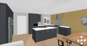
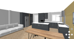
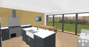
For the software DIY approach, there are free software options you can easily find online. IKEA has a kitchen design tool on its website for example. As does DIY Kitchens, which is what we ultimately used for our most recent renovation. (There may be others by the way — they’re just the ones we know about and have used.)
Here is our current kitchen that we designed ourselves. We used a number of design tools initially, such as Room Sketcher (SketchUp is another good option but there’s quite a learning curve), and eventually settled on using DIY Kitchens’ online design tool to create the final design. We subsequently augmented a PDF of this with more detail as to where appliances and shelving were to be located so the kitchen installers knew exactly where everything was to go. You can see in the below a PDF mark-up (the blue text) we added to make explicit the distance requirements for where the island units need to be installed relative to the wall base units.
Kitchen Design Using DIY Kitchens’ Online Planner

3D Kitchen Design Renders Using DIY Kitchens’ Online Planner
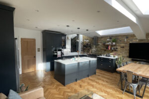
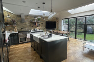
Kitchen Design Implemented
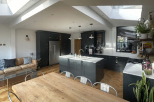
Kitchen Design Timing Tip
Kitchen designers don’t seem to be interested in discussing your kitchen plans too far in advance of when the kitchen may need to be delivered to the site. That’s often fine if you’re just putting a new kitchen into exactly the same space an old kitchen was already in. If your room dimensions or layout depend on your kitchen design and/or vice versa though, then it’s going to be a problem as you need to develop your kitchen design in tandem with developing the design of the room dimensions and layout.
Take our recent ground floor extension as an example again. The decision to do a wraparound extension versus another option was in part driven by the kitchen design. The kitchen design was also in part driven by that decision and other structural elements. Where structural beams and skylights were to go impacted the kitchen design. Likewise what kind of rear glazed doors we would have and what width and height they would be.
If whatever design decisions for the space your kitchen is to go into are in part dictated by the kitchen design or vice versa, be sure you don’t leave the kitchen design to later in the overall process. If you get resistance from a kitchen designer, you’ll need to emphasise why the kitchen design needs to be done sooner rather than later. If that fails, you’ll need to find a different designer or DIY.
There’s plenty of information out there already about kitchen design so we’ll leave it there. As with electrical and heating plans though, there are a lot of considerations that go into kitchen design and it’s easy to go wrong. If in any doubt, it’s probably better to get professionals involved.
Bathroom Designs
Bathroom designs are very similar to kitchen designs but usually much simpler.
You can engage a professional designer to do the work for you, to assist you or you could DIY.
If you DIY, again, it doesn’t need to be fancy. You can use the grid paper approach or use free online software.
Here, for example, is a simple 2D design layout we created for our recent loft conversion using Room Sketcher. We used the free version, which is basic but enough to create the layout design plan (one of many possible layout options we laid out using the software). We then sent this to the architectural designer, who reflected it in their CAD drawings.
Loft Conversion Bathroom Layout Design Using Free Software

Loft Conversion Bathroom Layout Added To CAD Drawings

Installers Need Clear Direction
A quick tip — be sure to include all relevant dimensions in whatever drawings that will be used by whomever is doing the plumbing and sanitaryware installation. We had a bit of an issue with our loft bathroom. The 1st fix fittings for the toilet and the sink where placed much too close to the pocket door which would’ve resulted in a tight squeeze upon entering the bathroom. Luckily we caught it before 2nd fix. The CAD drawings really should’ve reflected the critical spacing measurements, like our free software layout design does.
Implementation Of Loft Conversion Bathroom Layout Design

Much like our kitchen design above, it may be helpful to provide an elevation drawing showing the preferred location of things on a wall. For our loft bathroom shown above, we specified the height the mirror was to be hung and provided the dimensions of the wooden vanity unit. The plumbing team then just used their common sense and the usual rough heights for the location of the sink tap and the shower pipes.
The wall elevation elements for the renovation of our main bathroom was more complicated though so we provided a simple DIY scaled elevation drawing for that.
Scaled Elevation Plan For Main Bathroom Wall

Implementation Of Elevation Plan For Main Bathroom Wall

Other Rooms
You may also want to consider preparing designs and drawings for any other spaces where you think it may be beneficial enough.
Some people engage interior designers to just handle everything for them and those professionals will prepare whatever designs and drawings you may need to communicate plans to those implementing them.
You could alternatively take the DIY approach again using grid paper or free online software.
Garden Design
If you’re doing any significant landscaping, it may be worth getting a garden designer involved to help you with the design and prepare garden design drawings.
Garden design drawings set out the proposed landscape design, depicting any structural elements and hard-landscaping (structural elements, drainage, etc) and soft-landscaping (planting, etc). A garden designer will also help with preparing a planting design, which sets out the proposed planting specifics for the garden.
Sometimes whoever you use for your architectural plans may be willing and able to pull together garden drawings and specifications for you also. Likewise, some contractors will also offer this service along with doing the landscaping work. Maybe that’s the right option for your project for one reason or another. It’s worth giving consideration though to whether they are the right people for such jobs, given that there are plenty of good qualified and experienced garden designers and landscapers out there who may be much better suited.
You could also try the DIY approach of course. Many garden designers use SketchUp. There’s a free version you can try out. It’s tricky enough to use for a newbie and the free version is quite limited compared to the paid. There are plenty of training videos and other resources online for SketchUp though.
Finding Professional Services
For any services that are going to require in-person time or activities, you’ll ideally want to focus on finding local people to keep costs down and make your life easier.
The main options for finding professional services are generally the following:
When considering engaging professional services like an architect or a structural engineer, it’s wise to check some background information first in the same way that you would for engaging a contractor. Things can go wrong with designs and drawings so you should check for reviews and ideally references and at least be sure that the person or business you plan to work with is properly qualified and has the requisite business insurance in place for the work they do.

A Small Tip For Big Tips
If Renoviva has helped you, you can help Renoviva by leaving us a tip.


Make Connections
Come mingle with other renovators like you. Get support and share your experiences.